Ball Bonding vs Wedge Bonding
 back
back
For many years, wire bonding has been the most robust and commonly used method for chip-to-die interconnection of lead-frame, integrated circuit (IC) packages, RF microwave packages and optoelectronic packages.

A question often gets asked concerning what kind of application we use: ball bond or wedge bond? Why would a process engineer choose a wedge bonder over a ball bonder or vice versa? This has been the question by most process engineers because, generally speaking, electrical characteristics of the package are affected by the method of wire bonding. However, there are cases where certain packages have physical constraints such as temperature limitation (low heat or no heat applications), use of aluminum wire instead of gold, use of ribbon instead of wire and fine pitch application. This is where the proper selection of wire bond process comes into play.

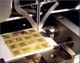
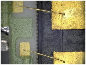
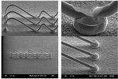
orms the wire into a flat elongated shape of a wedge, however depending on the type of wedge tool used, the shape can sometimes have a cross groove (typically for 1 mil gold wire). Unlike ball bonding, the first bond for a wedge bond does not have a ball, which is why this wire bonding process is called wedge-wedge bonding.

lude high-power applications, RF microwave, optoelectronic packaging, BGA, QFP, SOP, MCM hybrids and temperature-sensitive applications. Wedge bonding speeds typically fall within 3-6 wires per second, comparatively slower than a ball bonder.
“Recommend”
- Come and Meet Us at ECOC Exhibition 2024 from September 23-25 and Discover Our Latest Releases
- 400G/800G Connectivity for Data Center/HPC Solution
- 800G QSFP-DD Passive Direct Attach Copper Twinax Cable
- 800G Twin-port 2x400G OSFP to 2x400G OSFP InfiniBand NDR Finned Top Active Copper Cable
- 800G OSFP 850nm MMF Active Optical Cable 50m
- Come and Meet us in the exhibition OFC 2024--800G 2x SR4 OSFP Optical Transceiver/800G OSFP ACC

 Sales@tanlinkoptics.com
 86-18720073189
 3Fl, C#, Innovative Industrial Zone, Xinan San Rd, Baoan District, Shenzhen,China, 518100
